Product Description
Specifications:
Technology : GaAs pHEMT MMIC ( Gallium Arsenide - pseudo High Electron Mobility Transistor - Monolithic Microwave Integrated Circuit )
| Parameter | Unit | 0.8 GHz | 0.9 GHz | 1.0 GHz | 1.7 GHz | 1.8 GHz | 1.9 GHz | 2.0 GHz | 2.1 GHz | 2.2 GHz |
| Small Signal Gain | dB | 19.6 | 18.7 | 17.9 | 13.8 | 13.5 | 12.9 | 12.7 | 12.2 | 11.9 |
| Noise figure | dB | 0.52 | 0.55 | 0.79 | 0.75 | 0.81 | 0.83 | 0.90 | 0.91 | 0.98 |
| Output IP3 | dBm | 38.4 | 38.5 | 39.0 | 39.2 | 39.5 | 39.5 | 39.8 | 39.8 | 39.9 |
| Output P1dB | dBm | 22.3 | 22.4 | 22.5 | 22.6 | 22.6 | 22.7 | 22.7 | 22.7 | 22.7 |
| Input Return Loss | dB | 17.1 | 17.5 | 17.5 | 17.5 | 17.5 | 18.5 | 18.5 | 18.5 | 18.0 |
| Output Return Loss | dB | 16.0 | 16.0 | 15.5 | 14.0 | 14.0 | 14.5 | 15.0 | 15.5 | 16.0 |
| Reverse Isolation | dB | 24.5 | 24.0 | 23.0 | 18.5 | 18.5 | 18.0 | 18.0 | 17.5 | 17.0 |
- Antenna (preffered), or Antenna Mast
- Amplifier Input/Output Coaxial Cable
- Antenna Mounting Structure, i.e., Tower or Tripod, etc.
- Grounding Rod in Earth
TIPS:
(Tip-1) In case there is no coaxial shield ground connection at the Antenna : Use an "F-Type" coaxial ground block thru connector/union at the Amplifier Input or at the Output coaxial connector to provide a screw clamped connection for the grounding wire.
(Tip-2) The grounding wire can be electrically bonded to the mast, tripod, tower, etc., using a "U-bolt" style clamp. Once the grounding wire is attached, weather-proof the connection point by covering with silicone dielectric grease or silicone waterproof sealant and covering with electrical tape.
II. Grounding Rod, Solid Copper, Minimum 0.5-inch Diameter or cross-section, Minimum 8-feet length.
III. (2) Grounding Rod Clamps, for redundant connection of Grounding Wire to Grounding Rod.
IV. Another "F-Type" coaxial ground block thru connector/union near the ingress point of the home/structure.
IMPORTANT CONNECTION SEQUENCE ! :
1st -> All grounding system wire connections : Continuous length grounding wire connected from the Antenna to Grounding Rod, to home/structure ingress point grounding block.
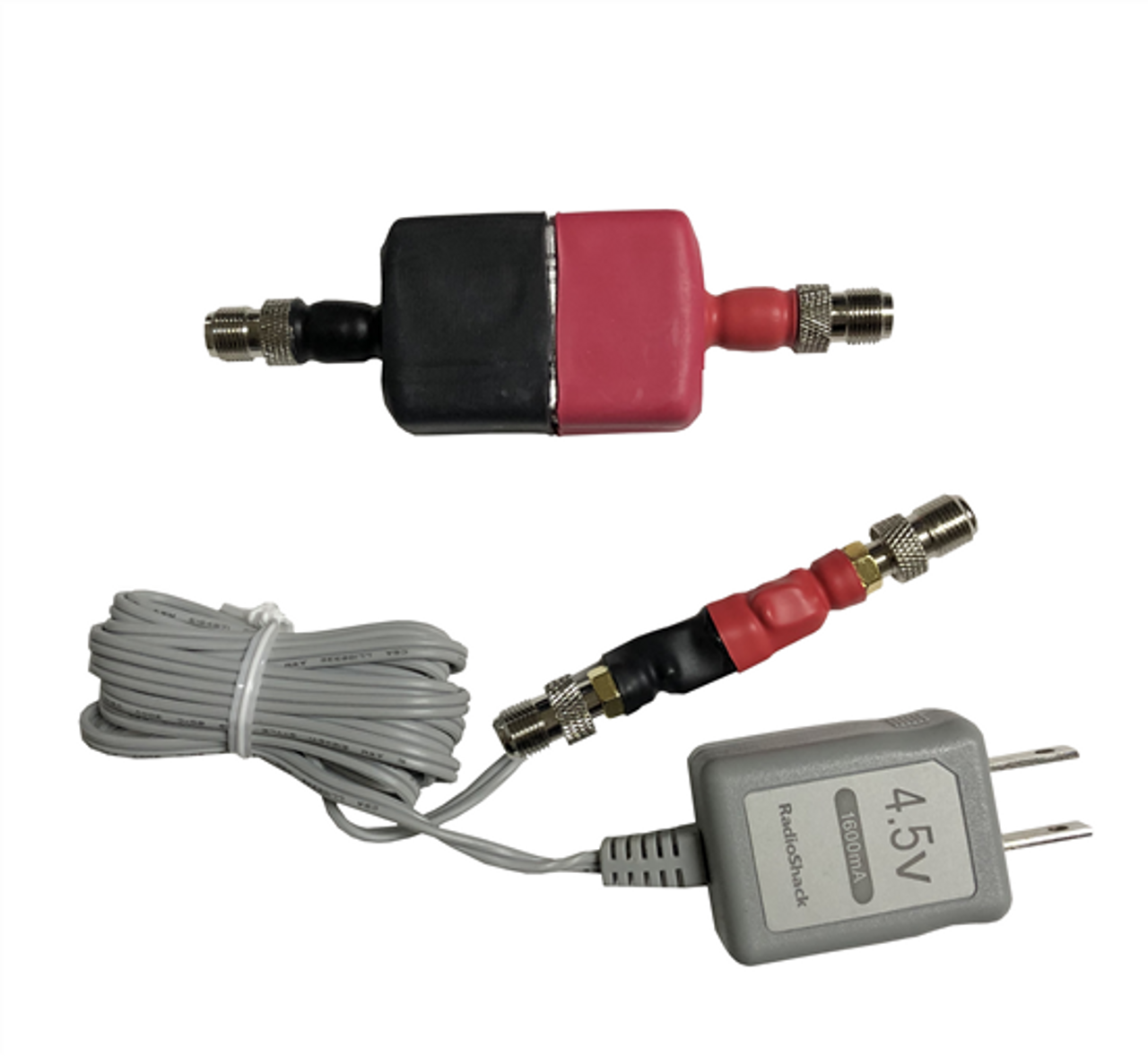
2nd -> Install all segments of the Coaxial Cable run from the Antenna/Amplifier grounding block to the building ingress grounding block, to the COAXIAL DC INSERTER+ AMPLIFIER CONNECTOR (color coded RED), and then to Reciever/Television Connector (color coded BLACK) DO NOT APPLY POWER YET.
3rd -> Insert the Amplifier into the coaxial cable end before the antenna, CONNECT OUTPUT SIDE (also color coded RED) FIRST, to assure ground discharge path through the coaxial cable downlead.
Do not connect the ULNA-0.55dB_NF/F Ultra-Low-Noise RF Amplifier UNTIL all other connections are installed, ONLY LASTLY CONNECT THE UNLA-0.55dB_NF/F Ultra-Low-Noise RF Amplifier Input to the Antenna (color coded BLACK) connector.
Note: Destructive electrostatic voltages can be present while handling and moving to the coaxial cable, and performing grounding connections, etc.
Do not introduce DC Power to the ULNA-0.55dB_NF/F Ultra-Low-Noise RF Amplifier, until ALL other connections are completed.
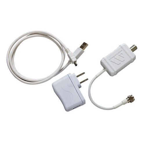
4th/LAST -> After all other connections have been made and there is a continuous coaxial cable connection from (a) the Antenna, (b) through the Amplifier, (c) through the DC Injector, (d) and to the Receiver/Television, (e) including all grounding system connections : Now turn on the Receiver/Television, and insert the AC Power Adapter into the AC power receptacle.
You have completed the installation.
**Some restrictions apply, not available to all address locations, 2 Day gaurantee not available to PO Boxes


